
Likewise one connected completely in parallel is known as a parallel circuit. The supply voltage in a series circuit is equal to the sum of the individual voltage drops.
Series And Parallel Circuits Youtube
Series Parallel Circuit Series Parallel Circuit Examples Electrical Academia
Simple Parallel Circuits Series And Parallel Circuits Electronics Textbook
Same as the series inductor combination the parallel combination of two inductors can be two types by using aiding method and by using opposition method.
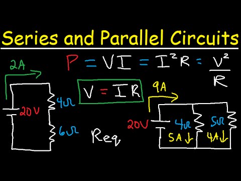
Series and parallel circuit formula. A circuit composed solely of components connected in series is known as a series circuit. Conversely they are said to be in parallel if the strain of the ensemble is their common strain and the stress of the ensemble is the. Series circuit I R1 must equal I Req1.
Then continue to replace any series or parallel combinations until one equivalent resistance R EQ is found. In series this is not the case. Example for Parallel Capacitor Circuit.
On this page well outline the three principles you should understand regarding series circuits. However the analysis of a parallel RLC circuits can be a little more mathematically difficult than for series RLC circuits so in this tutorial about parallel RLC circuits only pure components are assumed in this tutorial to keep things simple. The goal of series-parallel resistor circuit analysis is to be able to determine all voltage drops currents and power dissipations in a circuit.
In parallel circuit voltage remains same. A circuit starts and ends at the same point. Both series and parallel resonant LC circuits are used in induction heating.
Equation of RLC Circuit. If the following resistors were replaced with the values indicated. Consider a RLC circuit having resistor R inductor L and capacitor C connected in series and are driven by a voltage source V.
So for example in the case of DC the circuits can also be divided into three groups such as series DC circuit parallel DC circuit and. Lets try another more complex resistor combination circuit. A circuit is composed of conductors wire power source load resistor and switch.
Parallel circuits are the simplest electrical circuit to wire. Refer to Figure 5A. The general strategy to accomplish this goal is as follows.
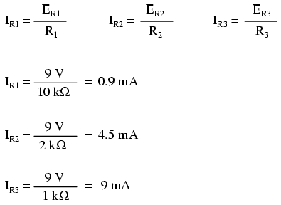
Resistance inductance capacitance and voltage are known quantities but current and charge are unknown quantities. The total resistance in a parallel circuit is always less than any of the branch resistances. Assess which resistors in a circuit are connected together in simple series or simple parallel.
This parallel resistor calculator calculates the total parallel resistance of a circuit. The formula to calculate the total parallel inductance is. This article will mainly introduce these two connection methods including their definitions formulas circuit diagrams examples and identification methods.
Find the equivalent resistance R EQ for the following resistor combination circuit. This calculator allows up to 10 different resistor values. In the below circuit diagram there are three capacitors connected in parallel.
C 2 1uf and C 3 01uf So C T 47 1. In circuit b we have resistors R 1 and R 2 combined to get 132Ω. C T C 1 C 2 C 3 Where C 1 47uf.
Examine the circuit diagram to make this assessment. For one the total resistance of a Parallel Circuit is NOT equal to the sum of the resistors like in a series circuit. The components of the electrical DC circuit are mainly resistive whereas components of the AC circuit may be reactive as well as resistive.
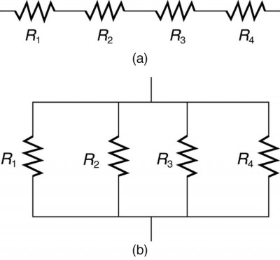
Current can only take one path. Any electrical circuit can be categorized into three different groups series parallel and series-parallel. In this tutorial well work out the formulas for resistors connected in series and parallel.
All of the loads are connected parallelly across voltage source so that loads have two common points with source positive and negative terminals. Formula for resistors in parallel is 1Rp 1415 1Rp 920. Formulas for Resistors in Series and Parallel.
Resistors are ubiquitous components in electronic circuitry both in industrial and domestic consumer products. The parallel circuit has very different characteristics than a series circuit. The two simplest combinations of resistors are series and parallel.
Formula for Adding Inductors in Parallel. More generally two or more springs are in series when any external stress applied to the ensemble gets applied to each spring without change of magnitude and the amount strain deformation of the ensemble is the sum of the strains of the individual springs. Use the appropriate list of major features for series or parallel connections to solve for the unknowns.
IntroductionResistors are usually connected in a circuit in various ways and the two most basic ways are series and parallel. Let Q be the charge on the capacitor and the current flowing in the circuit is I. As these capacitors are connected in parallel the equivalent or total capacitance will be equal to the sum of the individual capacitance.
A series resonant LC circuit is used to provide voltage magnification. Parallel Speaker Wiring combines all Speakers positive Speaker leads together and all - negative Speaker leads together. Determine whether resistors are in series parallel or a combination of both series and parallel.
Resistors In Series Formula. Resistors in Series and Parallel Example No2. Guidelines to Series-Parallel Combination Circuit Analysis.
The series behavior of the three elementary components of electronics has been detailed in our previous article Series RLC Circuit AnalysisIn this tutorial another association known as the parallel RLC circuit is presented. To calculate series resistance which you should use when connecting the out side of one resistor to the in side of another in a circuit use the formula Req R1 R2. If you want to compute the total resistance of less than 10 resistors just insert the values of the resistors you have and leave the rest of tbe fields blank.
Resistors are in series if the same current must pass sequentially through them. Series-Parallel Circuits Series-Parallel circuits can be more complex as in this case. Voltage divider rules states that Voltage divides in series circuit only.
When current is travelling through a parallel circuit the current can take various paths through the circuits such as to go through any of the branches containing the inductors. In the first section we present. Apply Kirchhoffs voltage law In this equation.
R 4 is in series with the newly combined R 12 and their added value is 512Ω. The total resistance of any series circuit is equal to the sum of the individual resistances. This time instead of the current being common to the circuit components the applied voltage is now common to all so we need to find the individual.
Rp 209 So Rp 2222Ω. The formular for Series Wiring is. Many circuits can be analyzed as combination of series and parallel circuits along with other configurations.
In circuit a we have our original complex circuit. Often in circuit analysis we need to work out the values when two or more resistors are combined. And now c we are left with R 124 in parallel with R 3.
Following is the table of formulas for parameters like. In this formula n equals the number of resistors in a series. Inductors in Parallel Combination.
Resistors can be arranged in series form too such that the current flows through the resistors in series. For the Aiding Method as seen on the left image the dot convention clearly shows that the current flow through the inductors is in the same direction. Adding Speakers in parallel decreases the overall resistance of the circuit.
In this article we will be discussing the series and parallel combination of resistors. A parallel resonant LC circuit is used to provide current magnification and also used in the RF amplifier circuits as the load impedance the amplifiers gain is maxed at the resonant frequency. The amount of current is the same through any component in a series circuit.
Electrical Electronic Series Circuits

Lessons In Electric Circuits Volume I Dc Chapter 5
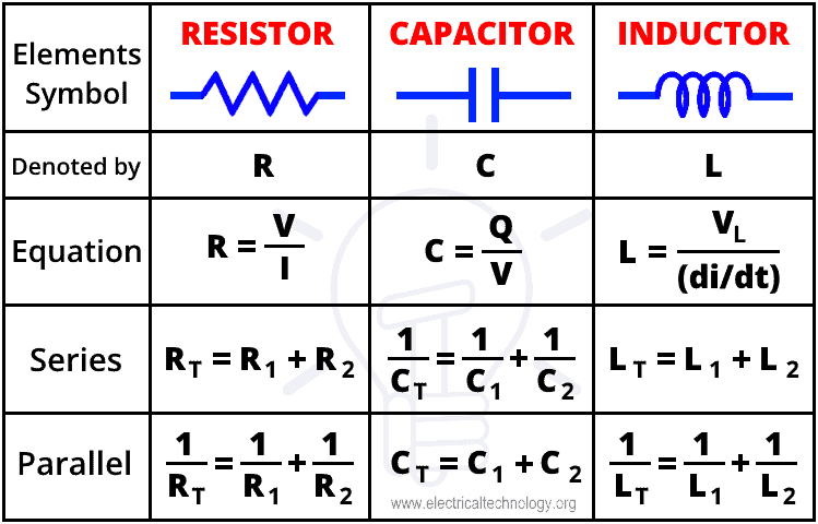
Resistor Capacitor Inductor In Series Parallel Formulas
Physics Tutorial Combination Circuits


Resistors In Series And Parallel Resistor Combinations
Resistors In Series And Parallel Physics
Series And Parallel Circuits Learn Sparkfun Com

4 Ways To Calculate Total Resistance In Circuits Wikihow


