
The ladder diagram starts with j j a normally open set of contacts labeled input A to represent switch A and in series with it j j another normally open set of contacts labeled input B to represent switch B. In the following block diagram input and output modules are connected through the brain of PLC ie.
Introduction Of Programming Logic Controller Plc Working Principles

Block Diagram Of Plc System Download Scientific Diagram

Block Diagram Of Plc Download Scientific Diagram
Ladder Diagram LD Function Block Diagram FBD Sequential Function Chart SFC Instruction List IL and Structured Text ST.
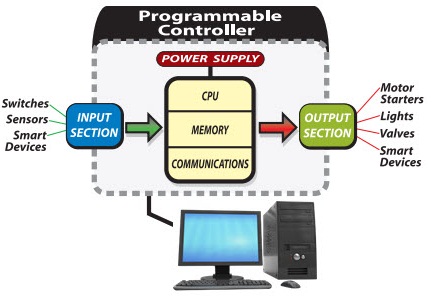
Plc block diagram. Color-highlighting of Ladder Diagram components only works of course when the computer running the program editing software is connected to the PLC and the PLC is in the run mode and the show status feature of the editing software is enabled. Now that we know what hardware is inside the PLC the next step will be to take a look at the software inside the PLC and how it runs. Block Diagram PLC Input Output Modules.
By passing data into this terminal you can display it in the chart on the Front Panel. To understand the different operations performed by PLC I am explaining each useful PLC component with the help of a block diagram in detail. Structured text ST the fourth language is a text-based language like Basic Pascal or C.
A block diagram is a diagram of a system in which the principal parts or functions are represented by blocks connected by lines that show the relationships of the blocks. Block flow process diagram for the production of benzene Turton et al 2012 In a fashion similar to the chemical process flow diagrams function block diagrams in PLC programming allow users to create a system that takes multiple inputs sends them through various instruction blocks and. In a process Figure 11.
Block diagrams are typically used for higher level less detailed descriptions that are intended to. The Function Block Diagram FBD is a graphical language for programmable logic controller design that can describe the function between input variables and output variables. PLCOpen has described using FBD in the standard IEC 61131-3.
NI LabVIEW software can communicate with a programmable logic controller PLC in a variety of ways. 12 Function block diagram The following function blocks explain IO information flow to and from the inverter in the PLC function. The Function Block Diagram describes a function between inputs and outputs that are connected in blocks by connection lines.
So if youve missed Part 1 you may want to read that article first and come back and continue with this part. They are heavily used in engineering in hardware design electronic design software design and process flow diagrams. Programmable Logic Controller PLC is a kind of computer that is specially designed for industrial control.
Youll also see how a VFD is related to a PLC in a wiring diagram. Central Processing Unit CPU. The Function Block Diagram which is also a graphical type of language.
PLC Architecture Block Diagram. The list of basic components are. It is a simple and graphical way to program any functions together in a PLC program.
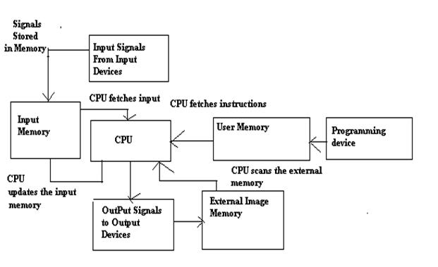
The block diagram of PLC consists of different components. The Inputs are represented by x y and z while the compliments are. Basic Block Diagram of PLC System.
This one is a graphical language like LD and uses blocks to represent functions with lines connecting them. An FBD helps us determine the function between output variables and input variables via a set of rudimentary blocks and diagrams that are connected with arrows known as connections. Programmable logic controller PLC is a control system using electronic operations.
A wiring diagram is an electrical print that shows connections of all components in a piece of equipmentA schematic diagram is a type of drawing that illustrates the electrical connections and functions of specific circuit arrangements with graphic symbolsA ladder diagram is a diagram that explains the logic of the electrical circuit or system using standard NEMA or IEC symbols. In the project explorer expand the OPCItems library and select the Sine1 shared variable. In this article youll learn about the PLC and its modules wiring diagram.
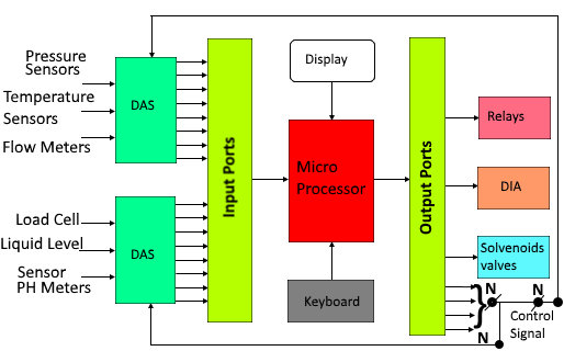
This input module is connected with the CPU for the initial automated processes. The block diagram of a typical industrial control system is shown in Fig 11. A Simple Ladder Diagram with NO and NC Contacts.
The scan cycle is the cycle in which the PLC gathers the inputs runs your PLC program and then updates the outputs. Modbus is a serial communication protocol published by Modicon in 1979 to communicate with PLC and was then extended to the TCP protocol. Industrial Control System control system the controller always plays a signi cant role to transact the operating conditions of.
A Functional Block Diagram abbreviated as FBD is a graphical representation of a functional process via blocks and diagrams that is easier for a reader to understand and interpret. Function Blocks were originally developed to create a system that you could set up many of the common repeatable tasks such as counters timers PID Loops etc. A function block is a program instruction unit that when executed yields one or more output values.
You can clearly see the logic diagram is developed using the AND gates and the NOT gates. Data flow is from the input devices through the CPU processor and then to the output devices. The input device provides a signal to an input module.
The functional block diagram which is a type of the block diagrams can be represented as a combination of an ordinary functional block diagram and a flow chart at the same time. Every PLC has a scan time and a scan cycleThis is how the PLC and the software inside the PLC works. Functional Block Diagram FBD is a simple and graphical method to program multiple functions in PLC.
Modbus became one of the de facto standard communications protocols in the industry because its availability. Inputs and outputs of the blocks are wired together with connection lines or links. Notice the icon on the Block Diagram which represents the chart on the Front Panel.
You can use one of so many different specific functional block diagrams technics in order to build different software development methodologies. A simple counter application in the programmable logic controller PLC using a counting example on conveyor motor and proximity sensor. Each component has associated specific functions and operations in the PLC.
The Block Diagram is where you build the behavior of your application. Input and output variables are connected to blocks by connection lines. New parameter-setting dialogues reduce setup time and with standard function blocks in IEC 61131-3 structured text or conventional ladder language CX-Programmer makes development of PLC programs a simple drag drop.
ST is powerful and can do more low-level processing than the graphical options. Function Block Diagram is easy to learn and provides a lot of possibilities. The CPU processor also exchanges data with the program and data memory.
Its easy storing procedures handy extending principles. Figure 18a shows an AND gate system on a ladder diagram. 3 to 8 line Decoder has a memory of 8 stages.
Bharadwaj July 24 2020. 8 PLC Function Applicable inverter model 11 Applicable inverter model This manual explains the PLC function of the FR-A800F800 series. One of the official and widely used PLC programming languages is the Function Block Diagram FBD.
Please confirm you want to. Development of your PLC program. A function is described as a set of elementary blocks.
Introduction to PLC Ladder Diagrams. The third PLC language is function block diagram FBD. It is convenient to use an AND gate as the basic decoding element for the output because it produces a HIGH or logic 1 output only when all of its inputs are logic 1.
The block diagram below explains the basic architecture of a PLC.
Plc Basics Block Diagram Types Applications Advantages And Disadvantageous

Programmable Logic Controller

Block Diagram Of Plc System Download Scientific Diagram
3

Plc Solutions Block Diagram Of Plc
Plc Programmable Logic Control Block Diagram Input Output Modules D E Notes

Programmable Logic Controller An Overview Sciencedirect Topics

Programmable Logic Controller Plc Programmable Logic Controller Logic Block Diagram


