
Electronic Circuit Symbols In electronic circuits there are many electronic symbols that are used to represent or identify a basic electronic or electrical device. It supports circuit drawing layout developing and circuit simulation.
1
Schematic Diagrams Mastering Arduino
Circuit Diagram Symbols Images Stock Photos Vectors Shutterstock
Its my st that just looking at the digital clock circuit diagram replicating it.
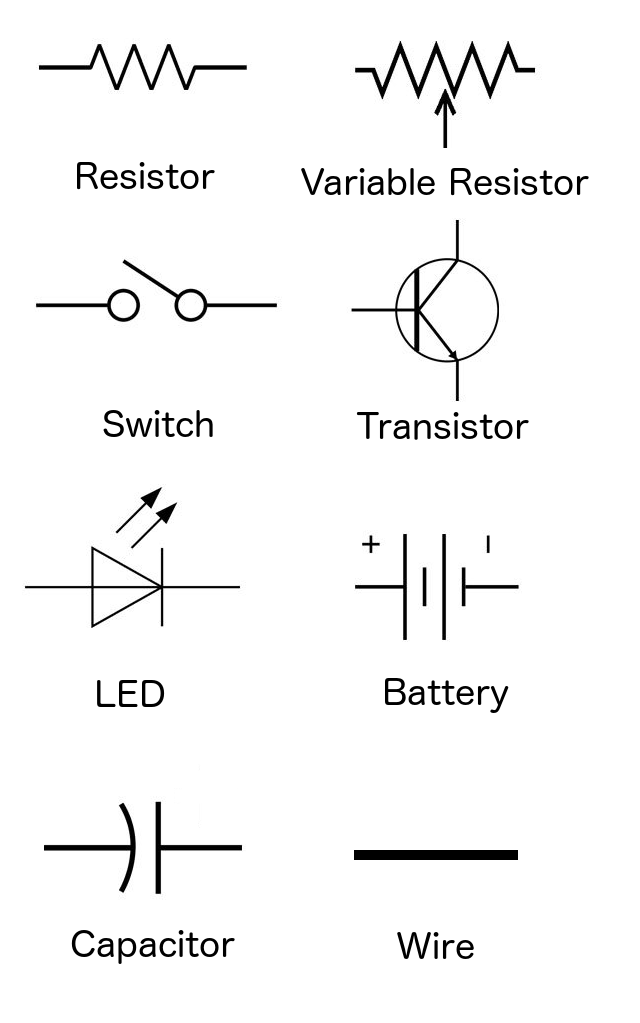
Circuit diagram symbols. The following symbols show the different components that can be found in an electrical circuit. Below is an overview of the most used symbols in circuit diagrams. To build a circuit you need a different diagram showing the layout of the parts on breadboard for temporary circuits stripboard or printed circuit board.
Although these component symbols change based on countries due to some common principles fixed by. After seeing a few circuit diagrams youll quickly learn how to distinguish the different symbols. This software is only for a beginner or a new entrant in the electronics circuit drawing arena.
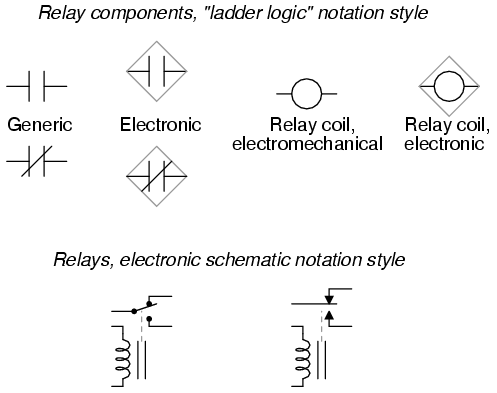
Relay Logic Circuits - SchematicSymbols. EdrawMax is an advanced all-in-one diagramming tool for creating professional flowcharts org charts mind maps network diagrams UML diagrams floor plans electrical diagrams science illustrations and more. The presentation of the interconnections between.
A line ladder diagram is a diagram that shows the logic of an electrical circuit or system using standard symbols. A circuit diagram is a visual display of an electrical circuit using either basic images of parts or industry standard symbols. A line diagram is used to show the relationship between circuits and their components but not the actual location of the components.
Circuit Component Symbols. The LCR circuit analysis can be understood better in terms of phasors. There are some standard symbols to represent the components in a circuits.
A circuit drawing allows you to visualize how components of a circuit are laid out. F 12LC Here we require a frequency between 88 MHz to 100 MHz. Line diagrams provide a fast easy understanding of the connections and use of components.
Circuit symbols are used in circuit diagrams showing how a circuit is connected together. Electronic circuit symbols are signs or drawings or pictograms of different components to signify electronic components in a schematic diagram of an electronic circuit. Symbol usage depends on the audience viewing the diagram.
A circuit diagram wiring diagram electrical diagram elementary diagram electronic schematic is a graphical representation of an electrical circuitA pictorial circuit diagram uses simple images of components while a schematic diagram shows the components and interconnections of the circuit using standardized symbolic representations. All these symbols are linked with straight lines that represent the electrical wires. The symbol for a battery is shown below.
Electrical symbols or electronic circuits are virtually represented by circuit diagrams. Today circuit symbols and their usage has been pretty much standardised. These symbols are the primary component of the circuit diagram and without these symbols the circuit diagram can never be completed.
You Will Love This Easy-To-Use Diagram Software. An electronic symbol is a pictogram used to represent various electrical and electronic devices or functions such as wires batteries resistors and transistors in a schematic diagram of an electrical or electronic circuitThese symbols are largely standardized internationally today but may vary from country to country or engineering discipline based on traditional conventions. A resistor restricts or limits the flow of electrical current.
In this article we will tell you about the essential circuit symbols you should know. The actual layout of the components is usually quite different from the circuit diagram. This gives value of C6 to be around 12pF.
We know the frequency of oscillations is given by. These two different types of circuit diagrams are called pictorial using basic images or schematic style using industry standard symbols. Our circuit diagram symbol library is schematic and includes many icons commonly used by engineers.
A digital clock is shown named as circuit diagram of digital clock using counters. Another means of describing a circuit is to simply draw it. We will also recommend you to make circuit diagram symbols using the well-known software the EdrawMax.
A fixed resistor has a resistance. Design of Oscillator Circuit. Schematic symbols are used to represent different electronic components and devices in circuit diagrams from wires to batteries and passive components to semiconductors logic circuits and highly complicated integrated circuits.
Circuit Diagram Examples and Symbols. A circuit diagram is also known as an electrical diagram elementary diagram or electronic schematic. An LCR circuit also known as a resonant circuit tuned circuit or an RLC circuit is an electrical circuit consisting of an inductor L capacitor C and resistor R connected in series or parallel.
This enables anyone to read a circuit diagram and know what it does relatively quickly. An electric circuit is commonly described with mere words like A light bulb is connected to a D-cell. A large and a small line is suppose to represent one battery cell so that the image below would suggest a two-cell battery of 3 V.
Lines connect fuses switches capacitors inductors and more. This article gives some of the frequently used symbols for drawing the circuits. A Selection of tank circuit components L1 and C6.
A final means of describing an electric circuit is by use of conventional circuit symbols to provide a schematic diagram of. Let us select a 02uH inductor. Each electronic component has a symbol.
Here we select a variable capacitor in the range 5 to 20pF. These symbols are used in the 2D and 3D representation of diagram circuits. A relay logic circuit is a schematic diagram which shows various components their connections inputs as well as outputs in a particular fashion.
Circuit diagrams can be created with thousands of possible shapes and icons and Lucidcharts circuit diagram maker has all the bells and whistles to ensure you have everything you need to create an industry-standard diagram. They are mostly used to draw a circuit diagram and are standardized internationally by the IEEE. In relay logic circuits the contacts NO and NC are used to indicate Normally Open or Normally Close relay circuit.
SmartDraw comes with thousands of detailed electrical symbols you can drag and drop to your drawings and schematics. They provide access to some basic and important components too. Later when you come across symbols you dont know you can come back here to identify what it is.
Digital Clock Circuit Diagram of different kinds have been built by countless hobbyists over the world. A circuit diagram is a simplified representation of the components of an electrical circuit using either the images of the distinct parts or standard symbols. A circuit diagram or a schematic diagram is a technical drawing of how to connect electronic components to get a certain function.
It is available for free download. Circuit Diagram is an open-source and free software used to design electronic circuit diagrams. Circuit and Logic Diagram.
Dia Dia is a basic drawing software suitable for drawing block diagrams.
Lessons In Electric Circuits Volume V Reference Chapter 9
Circuit Symbols Of Electronic Components Electrical Electronic Symbol

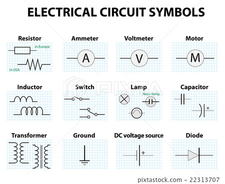
Common Circuit Diagram Symbols Stock Illustration 22313707 Pixta

Electricity Circuits Symbols Symbols

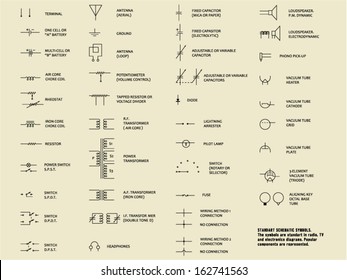
Standardized Wiring Diagram Symbols Color Codes August 1956 Popular Electronics Rf Cafe

Schematic Basics Part 1 Search Place Move Eagle Blog
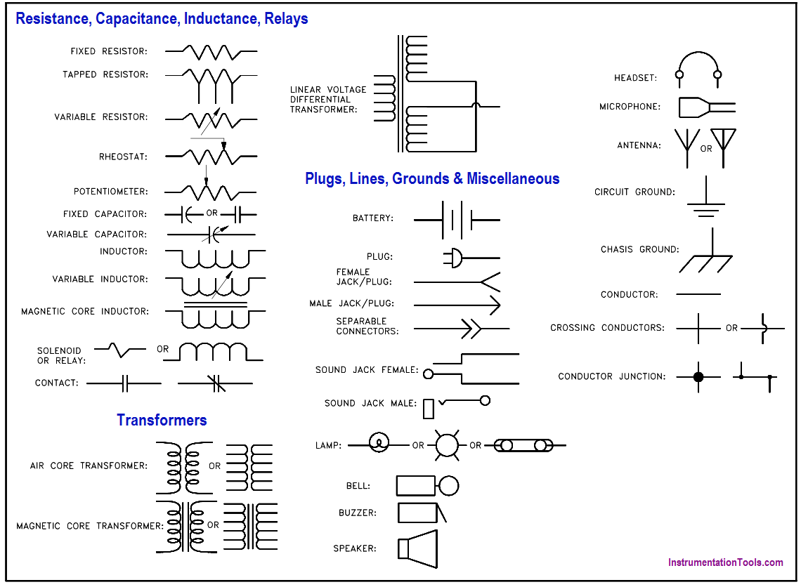
Electronic Diagrams Prints And Schematics Instrumentation Tools
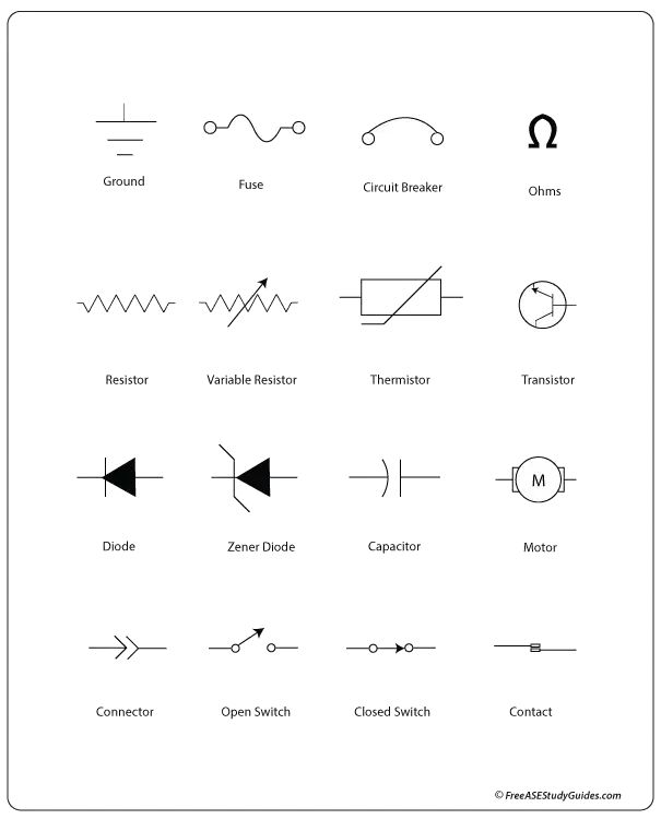
Common Automotive Diagram Symbols


